12.31.2007
the stribe project forum
I made a Stribe Project Forum - please join! I'm using it to keep track of all the details, and hopefully keep the project organized as more people get involved.
(Also started to set up a mediawiki but not much there, yet - if anyone feels like expanding on it it's here and will eventually be updated).
Right now the forum's a repository of notes and facts about the Stribe project so far. I hope it will be a landing spot for people interested in participating in the project in one way or another, either by building or buying a Stribe, improving and expanding the (admittedly incomplete and amateurish) firmware and Max patches, or just watching from the sidelines.
http://soundwidgets.com/smf/
12.30.2007
stribe update

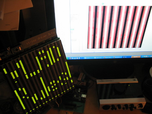
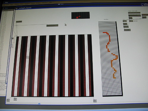
screenshot of _stribe_howto.mxb (virtual stribe) in action - click for big view
I'm plodding forward on several fronts at once, mostly doing boring stuff like trying to put together a stribe wiki and/or forum type thing as well as juggling parts to build a handful of prototypes for development. Today I took some time to clean up the Max code so far and it looked so pretty I had to take a picture.
Meanwhile Vlad Spears (author of Balron and the Daevel behind Daevelmaker Plugins) wrote a Max abstraction to translate values from the Max matrixctrl object into the message format expected by the Stribe, something I'd been struggling with trying to solve in firmware.
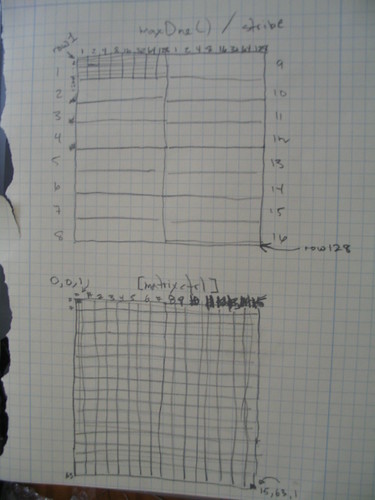
The pieces were all there in Max but I needed that one final bit and Vlad was able to do it from a few vague e-mails and a .jpg of a scrawled napkin drawing. Amazing.
12.27.2007

12.20.2007
andrew fentem fentix cube

It's so weird I was just at a party or something talking to someone about how you could do something like this with OLEDs...
This guy is doing a lot of cool stuff.
12.14.2007

some guy rocks a monome 256 running 'flin'
Looks like he has a 40h, too. With a quick peek at the Buchla box in the corner.
(Earlier this was posted as being Trent Reznor but that was an error. Neither having met Trent nor seen him up close I didn't realize this is actually Alessandro Cortini. It was on the nin youtube page so I just figured it was him - my apologies to all.)
12.06.2007
Learning Max/MSP
I'm learning Max/MSP. I sometimes find the Cycling74 site a little intimidating because there's just SO much information, and the online Tutorials run a bit long for my ADD brain, so I went looking for some other resources. I found this great online set of Max tutorials. Much more condensed - skips right to relevant stuff and tells you exactly what you need to know to get started learning Max, and is divided into logical 6- to 12-page chunks. The chunks range from a great basic Introduction to Max (required reading) to more esoteric: Max and Chaos.
Highly recommended reading: Peter Elsea's Max Tutorials
Highly recommended reading: Peter Elsea's Max Tutorials
12.04.2007
Stribe 0.4 circuit - 180 degrees of change
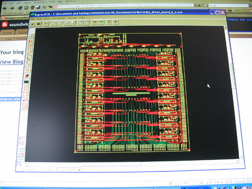
I've made a major revision to the Stribe circuit boards, rotating them 180 degrees to better reflect the way Max/MSP addresses arrays and to make my firmware simpler (and hopefully faster). Short version: 0,0 is the top left corner now instead of the bottom left. I also moved the logic circuit to the top of the board, which is the same place the touch-strips attach. So now I avoid 8 long trace runs as well as making a better location to add a MIDI circuit or other interface connectors (8 synth-type voltage triggers, anyone?).
[circuits]
Meanwhile I've also been working on the firmware and the Max patches, getting everything talking to everything else. I'm borrowing lots of example code as well as nabbing a few of Brian Crabttree's handier bits of code (the bits I can understand). I'm building a "virtual stribe" with the matrixctrl object.
[code]
Feel free to take a look and offer your suggestions.
11.27.2007
40h review in TapeOp

I wrote a review of my favorite toy for my favorite magazine: TapeOpArticle.pdf
...or find the print edition of TapeOp #62 Nov/Dec 2007.
I guess my review's a little late to the party since the 40h is no longer available and monome has moved on to sell out the "256" and will start taking orders on the "128" soon.
Update: monome sold-out their latest batch of 100 40h kits... in less than 24 hrs!
11.25.2007
Stribe 0.2
A video of the latest stribe (rev 0.2), running a really basic Max program. It sounds very Star Trek-like - maybe that's due to the Hammond-ish sound of the synth.
11.23.2007
11.19.2007
11.17.2007
Stribe driver board 0.2 build and test

I got the production-style (still prototype) solder-masked green driver board earlier this week and assembled it today. I plugged in an Arduino MINI and Arduino MINI USB and soldered everything up - and it works! Well, mostly. Had a couple of small glitches but nothing major and I'm glad I caught them before I made these in any kind of quantity. V 0.3 will be even better with several tight clearance issues solved.

See more pics
11.11.2007

11.08.2007
robert henke - cyclone

"Interactive Installation for eight speakers and LED matrix"
This has a custom monome 256 at its' core.


10.16.2007
small DIY touch control box

"nuibox An affordable small form factor vision sensor." Looks intriguing - the post lists parts and looks to have steps to build the box but most of them are incomplete. Post in progress?
10.15.2007
10.10.2007
stribe 8 prototype works!
So far the firmware just sends serial data into Max which in turn sends out weird noises and 8 values via an OSC string, but it's a start. Next step is to accept incoming OSC commands to drive the display from software, and to write some cool apps in Max and Reaktor that take advantage of the unique properties of the controller.
I've been trying to learn enough Max to get the monome and stribe running from inside the same app, and I almost have it working by combining an app I wrote for the stribe with a monome app - but I gots me some learnin' to do before I can really get going on my main ideas for this. But now the pieces are all here.
9.29.2007
Mochika hand made analog synth/sequencer

"This synth features one square and saw waveform VCO (voltage controled oscillator) with a huge pitch range, from subsonic to ultrasonic sound. One square and triangle waveform LFO (low frequency oscillator), that modulates the VCO for the vibrato effect creating old school arcade Atari-like sounds. White noise generator that triggers the VCO and can create percussion like sounds. 8 step Sequencer with note on/off switch and pitch knob for each step. It has a 1/4 inch audio output, 1/4 inch CV Output (to control other analog gear), 1/4 inch Clock input (gate in to synk whit an external clock), 1/4 inch Gate/clock output. Also the instrument is ligthed 2 with green leds that indicates the LFO and Sequencer Rate, and 8 blue leds to indicate the step that is being played. Very useful when you play it on a dark stage. The Analog Sequencer is packed in a cool cristal acrilic case that shows all the hand made analog circuitry. The instrument is powered directly from 110V or 220V AC. Dimensions: 230mm(W), 170 mm(D), 80mm(H. incuded rubber feet and knobs)" - Atomo Labs
9.27.2007
monome 256's going fast
conway's life from tehn on Vimeo.
Yesterday monome started taking pre-orders for their $1400 "256".
Out of a total of 100 units in this run, 55 remain.
9.24.2007
triiibe + phineus

The Casilio triplets (above) used some phineus music for the intro movie on their new website: triiibe.com
stribe limps forward
The first 30 seconds is where I plug the Wiring board into the wrong power supply and the Stribe sucks amps and fries 1/2 my led driver (MAX7221) ICs. An expensive mistake @ ~$8 each. Fortunately I only had one side plus the one on the top right hooked up. So while I await new 7221's I limp along with 7 partially-working chips. At the end of the video you can see where the cursor code is working - a couple of wiring glitches cause some overlap but this actually shows some interesting possibilities. What's hard to see from the video is that when two cursors are sharing a column they appear at 2 different brightnesses.
I'm working on a "hold" mode where the cursor will hover in place for a few cycles after you let go. I will also make the cursors height-adjustable and add "meter" mode where I fill in the leds up from the bottom. I like the way the transitions between led colors look so I will make the next led board in multiple colors of bar-graph. This time I'll use IC sockets instead of soldering all the meters in so I can re-arrange them to taste. Maybe red at the top and bottom of each column, then yellow then green across the middle. Or have each column a different color. Or I could use diagonals, or a curve....
9.21.2007
swe-e-e-et

panel dimensions: 60 x 91cm / 23 x 35"
This is the front panel for a diy analog synthesizer kit called the ASM-2 Wizard, one of many intriguing options available from Elby Designs.
The device is available as bits or as a bundle and everything in between. Either way that's a lot of solder.
The intriguing thing about the ASM-2 is that the design includes, on one board, multiple sections representing the components of a true modular. These sections can then be built (or not) at your own pace, then wired up to a panel of your own design, or opt for the full-on Wizard which includes the gorgeous pre-printed front panel.
ASM2-Wizard Full Kit: "Includes:-ASM-2 pcb and component kit, IC Socket and Crimp kits, Alpha 16mm pots, 1/4" jacks, PolyDAC(X) pcb and component kit, RawDC pcb and component kit, 2 Octave pcbs and component kits, and a front panel. You WILL need to supply a cabinet, a dual 18VAC transformer and a mains connectivity kit." Just over $1200 US.
Assembly manuals and lots of designs are on their site: Elby Designs
9.15.2007
mmmmm, blue

"Flower Electronics designs and manufactures modular synthesizers. Our goal is to produce unique musical instruments with ultra high build quality, and total freedom of sound."
Flower Electronics
I've been thinking about making the Stribe standalone as well as computer-connected. I've been wrassling with computer issues more than I've been building, and I'm gonna be more than ready for a break from this glowing screen by the time I get this thing working. Maybe a hardware/analog option would get faster results and be more fun - hook it up to analog modular synths and sound modules and stuff. Have both control voltage and MIDI output. It's only 8-controllers, shouldn't be that big a deal, maybe even use a kit like from Lady Ada.
So now I'm looking around for small synth and sampler and sequencer circuits I could put inside the case along with the controller. Like maybe some knobs on the back. Make it 2-sided with a rubber bumper around the outside edge, filled with batteries. That could make it look like the tenori-on but maybe that's inevitable.

9.14.2007
9.13.2007
Technos Acxel - touch-controlled waveform

I'm not sure exactly how this thing works but it was made in 1987. Apparently you can touch the grid of leds to draw waveforms and do re-synthesis.
Here's a good article and here's a video demo:
9.12.2007
stribe progress, hardware and software
hardware:

Got the driver board today. It turns out I made a mistake and left out one hole next to each 7221. To work around it I had to install these resistors on the back of the board.

The top and bottom fit together perfectly, until I added the chips to the sockets, then I ran into clearance issues with the tops of the chips hitting the long legs of the led bargraphs coming thru the top board.
So I'm going in with snippers to each leg but might be doing some damage since everything is all soldered-up. I will go back and reheat the joints and hopefully that will be enough. If not I have another led board and more bargraphs on the way.

software:
Made progress with the Max programming last night. Got some great tips from Kid Sputnik and as a result was able to get the stribe strips to generate OSC messages, which actually show up in Reaktor! Now I have to do something with the messages - time to dig back into Reaktor programming.
9.09.2007
phineus + xenome/stribe prototype + Max/MSP
Well it's finally starting to sound like music. Soon there will be lights to guide the fingers..
Thermoesthesia (interactive art)
Temperature changes along with lighting in this interactive sculpture. via oddist
9.08.2007
hacking the monome 40h
While waiting for the new xenome/stribe driver circuit board to arrive, I've spent a couple days digging into the monome serial protocol, trying to understand it better and determine if I can use it for the xenome/stribe.
Couple things:
1) my device is upside down and backwards relative to the monome. See, when writing my firmware I started counting at the lower left corner and went up and right from there. My thinking was the xenome is essentially a bank of bargraphs, where 0 is at the bottom of each one, and they're numbered left to right. Then, when designing the led board, I saw that I would have to do a lot of fancy routing to treat each 64-led column with one MAX7221. But if I addressed the leds as a grid of smaller 8x8 grids all stacked together, it simplified wiring considerably. Basically I just made a grid of wires and was able to wire it as a 2-sided board with only a few strategic vias. So now my 0,0,0 is the lower left corner of the lower left 8x8 portion of a 64x16 grid, and 1, 0, 0 is the one on top of it, and so on. But the monome firmware starts with 0,0 at upper left, like a data array:

2) The monome firmware and serial protocol are super-clever. In fact everything about the monome is really kind of this brilliant compact jewel, the firmware and the software and the hardware all conceived as one. The design seems like an art thesis or a manifesto on computing, more than a way to simply make buttons blink on and off. It uses bitwise operations to build and parse the OSC messages, in a similar way to how you address the MAX7221 itself. The firmware sends and receives only 2 bytes in each direction, the monomeserial software does the rest.
As a semi-rusty C/C++ programmer it's been challenging for me to learn all this. It seems very custom-made for the specific device (an 8x8 grid of buttons that light up, driven by a MAX7219/7221 and an AVR chip), and the code is lightly commented. On the other hand, it's designed to scale to treat multiple grids, accept input from additional pots or encoders, and of course the real bonus: it's openSource, there's a community, and Brian has been super responsive to my many noobish questions on the monome forum.
So I'm learning a lot from this exercise, and there's certainly a lot I can borrow, but I might have to stick to my own firmware and a similar protocol. I can still make it compatible with monome apps via OSC.
Then again...
...Xenome is kind of a cool name. And I'm not doing anything even a little bit like genetic research. Well maybe a little bit. I dunno.
Anyhoo, things have been a little quiet on this blog but certainly not in the analog, er, real world.
I solved that problem with the strip values bleeding over onto eachother by adding a 10k resistor between signal and ground on each input. Pow, zap, fixed. Now I can bloop each channel seperately. Yay!
Then I went back to work on the led driver board, the one that's going to hold 16 MAX7221s and run my 112 led graphs. I'll link to the circuit board layout once I get the proto back from the manufacturer and make sure it works. I made some last-minute changes late at night right before I hit "order" and I'm hoping I didn't kill anything. I added a 20 pin header and ran the SPI interface to one half and power and voltages to the other. Kind of bad practice but I happen to have a box of 20-pin headers and sockets and ribbon cable so why get fancy. I can always skip the header and solder right to the original pads (which I left in place). So the boards should be here late next week.
9.01.2007
stribe
I've decided on a new working title for the touch controller project: "Stribe"
1) the name "xenome" is pretty much taken by a pharmaceutical company
2) "xenome" is a little too close to "monome"
Stribe means "stripe" in Danish. I like that it sounds like "scribe," and "strive," and that it doesn't mean anything particular in English. I think there's a shoe somewhere called this, and an athelete with it as a last name, but otherwise it seems unused. And who knows, maybe I'm part Danish.
Stribe nee Xenome time-lapse progress pics:

paper sketch + actual parts for comparison

breadboarding the MAX7221 + bar-graphs + Arduino

6 Spectrasymbol "hotpots" on top of stacked bargraphs. This showed that putting the pots right on top of the led bars is a bad idea for 2 reasons: 1) you can feel the joints between the bargraphs, 2) air bubbles appear between the uneven bargraphs and the sticker surface

These are 2 led boards. I designed the circuit layout in ExpressPCB and 3 days later they appeared in my mailbox.

I learned that I'd made the though holes around the edge too small for the pin headers I had planned to use. fortunately, the female headers fit. I had to file the edges of each header to get them to fit right up next to each other.

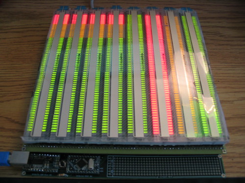
Here's the bottom of the assembled led board. That's uh, lessee, 2240 solder joints for the leds, plus 280 more for the pin headers. Went a bit cross-eyed. Learned there needs to be a bit more room between the led segments - but maybe that's because these are cheap. The board ended up slightly curved from the ceramic cases snugged right up against eachother. Higher quality parts might work better. Also, it was very fiddly getting the tiny legs of each bargraph to line up and go through the small holes. I don't have much room to make the holes a lot bigger but the higher quality name-brand bar-grpahs have thicker legs so I'll need to open these up a bit, too. One thought was to use IC sockets in place of all of the actual bar graphs, then insert the bar-graphs into the sockets. This would ease assembly as well as allow easy swap out for different colors or to replace a bad unit.

Here's the top of the assembled led board. I added a sheet of plastic cut from a paper binder - sticking the sensors onto this will make for a much smoother surface. Ideally, it would be great if the leds were all one piece, like little SMD leds embedded into a thin piece of plastic.

Here's the clear "softpots," installed. I was leaning away from these clear ones because the tactile feel of them isn't as nice as the yellow "hotpots" - but I realized I can put another layer over the softpots and they will still work. Which is great because now I can find a surface that has the touch and look I want - e.g. translucent, transparent, with different textures, possibly ridges or grooves to demarcate each stripe... not to mention that I could print stuff onto this layer. This layer could have different designs on it to provide help for different apps.

It's also good that I waited to finalize the circuit for the driver board. Now I see where I can include routing for the strips right on the driver board.
1) the name "xenome" is pretty much taken by a pharmaceutical company
2) "xenome" is a little too close to "monome"
Stribe means "stripe" in Danish. I like that it sounds like "scribe," and "strive," and that it doesn't mean anything particular in English. I think there's a shoe somewhere called this, and an athelete with it as a last name, but otherwise it seems unused. And who knows, maybe I'm part Danish.
Stribe nee Xenome time-lapse progress pics:

paper sketch + actual parts for comparison

breadboarding the MAX7221 + bar-graphs + Arduino

6 Spectrasymbol "hotpots" on top of stacked bargraphs. This showed that putting the pots right on top of the led bars is a bad idea for 2 reasons: 1) you can feel the joints between the bargraphs, 2) air bubbles appear between the uneven bargraphs and the sticker surface

These are 2 led boards. I designed the circuit layout in ExpressPCB and 3 days later they appeared in my mailbox.

I learned that I'd made the though holes around the edge too small for the pin headers I had planned to use. fortunately, the female headers fit. I had to file the edges of each header to get them to fit right up next to each other.

Here's the bottom of the assembled led board. That's uh, lessee, 2240 solder joints for the leds, plus 280 more for the pin headers. Went a bit cross-eyed. Learned there needs to be a bit more room between the led segments - but maybe that's because these are cheap. The board ended up slightly curved from the ceramic cases snugged right up against eachother. Higher quality parts might work better. Also, it was very fiddly getting the tiny legs of each bargraph to line up and go through the small holes. I don't have much room to make the holes a lot bigger but the higher quality name-brand bar-grpahs have thicker legs so I'll need to open these up a bit, too. One thought was to use IC sockets in place of all of the actual bar graphs, then insert the bar-graphs into the sockets. This would ease assembly as well as allow easy swap out for different colors or to replace a bad unit.

Here's the top of the assembled led board. I added a sheet of plastic cut from a paper binder - sticking the sensors onto this will make for a much smoother surface. Ideally, it would be great if the leds were all one piece, like little SMD leds embedded into a thin piece of plastic.

Here's the clear "softpots," installed. I was leaning away from these clear ones because the tactile feel of them isn't as nice as the yellow "hotpots" - but I realized I can put another layer over the softpots and they will still work. Which is great because now I can find a surface that has the touch and look I want - e.g. translucent, transparent, with different textures, possibly ridges or grooves to demarcate each stripe... not to mention that I could print stuff onto this layer. This layer could have different designs on it to provide help for different apps.

It's also good that I waited to finalize the circuit for the driver board. Now I see where I can include routing for the strips right on the driver board.
8.29.2007
xenome proto II - making some bad noises
sounbds a bit evil, and the leds don't light up yet, but I'm learning a lot from this 6-channel version
8.25.2007
8.22.2007

8.16.2007
Singing Tesla Coil
"This is a solid-state Tesla coil. The primary runs at its resonant frequency in the 41 KHz range, and is modulated from the control unit in order to generate the tones you hear... So just to explain a little further, yes, it is the actual high voltage sparks that are making the noise. Every cycle of the music is a burst of sparks at 41 KHz, triggered by digital circuitry at the end of a "long" piece of fiber optics.... What's not immediately obvious in this video is how loud this is. Many people were covering their ears, dogs were barking..."
- found on youtube: demjp8RqDA
Joe DiPrima and Duck demonstrate, explain the technical details, and tell the history of the Solid State Musical Tesla Coil
8.09.2007
8.07.2007
8.05.2007
LED-s Urban Carpet

"The LED-s Urban Carpet is a portable interactive installation using a non-traditional user interface. The installation represents a game with a grid of lights that can be embedded as a carpet into the urban context. A pattern of lights is generated dynamically that change in real time according to pedestrians movement over the carpet. In this case the pedestrians become participants that influence the generative process and make the pattern of LEDs change with the change of the location of one or more participants... ...This program is written using a Boid algorithm to simulate a flock of seagulls that follow the pedestrians as they move in different directions over the carpet." - interactiveinstallations.blogspot.com
8.01.2007
Your First Synth

"Building a WSG [Weird Sound Generator], while fun, is not a deeply scientific or religious experience. The WSG does not look or work at all like a synthesizer used by anyone whose name rhymes with either Cakeman or Bemerson. The WSG does not have a keyboard, it has a few knobs and switches. Do not expect to use the WSG in concert. The WSG makes mildly entertaining, droning beeps and boops... This is not even a shadow of a real music synthesizer but merely a fun little noise maker. It is designed to be built on a solderless breadboard and experimented with or put on a proto-board or PCB and placed into an outlandish case for fun by electronics hobbyists." - musicfromouterspace.com
7.31.2007
Fijuu2
Demo of the new 3D music-making software, Fijuu2. The player morphs forms with a PS2-style gamepad, which alter sounds that are then recorded to tracks. Fijuu2 is an open-source project and runs on Linux.
more info: http://fijuu.com
7.30.2007

7.28.2007
Tenori-On Demo
This is Yamaha's upcoming music toy/interface, the Tenori-On. Similar in concept to the monome but it is self-contained rather than requiring a computer and software, and it is transparent, so can be viewed from both sides. It will come pre-loaded with an assortment of programs and sounds. Of course it is not opensource like the monome, and the price is rumored to be over $1000.
Lots more details, here: http://en.wikipedia.org/wiki/Tenori-on
Circuit-Benders... heat up your irons!
7.21.2007

7.19.2007

Nice MS Surface demo
http://www.brightcove.com/title.jsp?title=933742930
Microsoft "invents" tangible computing. Still pretty cool.
Microsoft "invents" tangible computing. Still pretty cool.
7.11.2007

noce fears putnam
I was lucky enough to be at the debut performance of this intriguing act. Much of the music was made via monome 40h. Nicely recorded and a very enjoyable listen: nocefearsputnam.com
DIY EEG machine
 the OpenEEG project
"The OpenEEG project is about making plans and software for do-it-yourself EEG devices available for free (as in GPL). It is aimed toward amateurs who would like to experiment with EEG."
microbusiness usa

Inspired by the business model of monome.org, I did a bit of googling about microbusinesses and the opensource business model:
A nanocorp is a ruthlessly small business - Sohodojo
Wikipedia: Small business, Mesoeconomics, Micro-enterprise: "Broadly stated, a micro-business is a business started with as little capital as possible, or less capital than would be usual for a business. More precisely, the term is often used in Australia to refer to a business with a single owner-operator, and no employees."
Excerpted from the monome.org manifesto : "we strive for economic and ecological sustainability. careful design practice allows us to contribute to culture and preserve the environment by choosing domestic, high-quality, and responsible providers and production facilities. we acknowledge that our future will depend on our ability to support and maintain a local, regenerative economy."
eXtropia.com: "The open source business model relies on shifting the commercial value away from the actual products and generating revenue from the 'Product Halo,' or ancillary services like systems integration, support, tutorials and documentation."
Wikipedia: Open source hardware
Writings on Open Source Hardware - opencollector.org
the Open source Hardware project
MAKE:
Open source hardware, what is it?
Wanted: Nobody - Businesses with 0 employees use outsourcing to get the job done By Jim Hopkins, USA TODAY (December 11, 2006)
More:
Help Not Wanted - Rise of the nanobusiness
Small Is The New Big
LED notes

TB029 from microchip.com discusses multiplexing LEDs: TB029
Maxim APP NOTE 1880 from maxim.com: Charlieplexing - Reduced Pin-Count LED Display Multiplexing This application note discusses "Charlieplexing" -- a pin-count reducing multiplex technique used by the MAX6950, MAX6951, MAX6954, MAX6955, MAX6958, and MAX6959 LED display drivers.
Older article about power issues when driving lots of LEDs and a nice explanation of LED multiplexing to save pins: Don Lancaster's Tech Musings August 2001
Maxim APP NOTE 141: Data Multiplexer Adds Cursor To MAX7219 or MAX7221 LED 7 Segment Display Driver Abstract: The MAX7219 or MAX7221 7-segment LED display driver can highlight any one digit of its 8 digit display by adding a data multiplexer. This circuit intensifies the brightness of the selected digit to provide a cursor function for data entry as well as readout.
MAX6956: 2-Wire-Interfaced, 2.5V to 5.5V, 20-Port or 28-Port LED Display Driver and I/O Expander
MAX6956 Programming Guide
Using a Digital Potentiometer for Push-&-Hold Control-Setting Adjustments
Digital Potentiometers Replace Mechanical Potentiometers
Driving 4-1/2 Digit Meter Displays with MAX6958/59 LED Drivers
MAX7219, MAX7221
MAX6950, MAX6951
LED Manufacturers' Web Sites
Maxim Tutorials
I just received a couple sample MAX6969's. "The MAX6969 uses the industry-standard, shift-register-plus- latch-type serial interface. The driver accepts data shifted into a 16-bit shift register using data input DIN and clock input CLK. Input data appears at the DOUT output 16 clock cycles later to allow cascading of multiple MAX6969s. The latch-enable input, LE, loads the 16 bits of shift register data into a 16-bit output latch to set which LEDs are on and which are off. The output enable, OE-bar, gates all 16 outputs on and off, and is fast enough to be used as a PWM input for LED intensity control."
"Multiplexing doubles the MAX6974/MAX6975 drive capability to 48 LEDs."
code and schematic to run 8x8 led grid w/7219 and Arduino
Ok, here's an exact schematic for a 7219 8x8 led matrix and even a pre-made board is available: http://www.woe.onlinehome.de/e_projects.htm
7.09.2007

7.05.2007
semuta & marteleur - o my
or should I say oo la la?

...now that's what i'm talkin about!
servovalve.org
These are software-based musical instruments similar to Reaktor instruments but standalone. The website itself is also worth checking out (requires Shockwave) for a portfolio of less interactive but very beautiful sound/image/generative works. The names are in French I think.
Beat Blocks

"Beat Blocks is a tangible interface for a rhythm sequencer. The user is able to create and manipulate an 8-track drum loop (4 tracks in the featured prototype) on the fly by physically re-arranging blocks within a matrix. Each block is actually a sub-sequence identified by a patterning scheme." go here for more details and a video
hometown boy totally wired for steam

Childhood chum and early inspiration Jake Von Slatt has landed himself in the pages of Wired magazine! Meet Mr. Steampunk - Wired 6.29.07

As an impressionable highschool techno-dork, I remember tearing my gaze away from Von Slatt's lovely sister just long enough to admire his hand-made platter of vintage 2-button TV remotes, each wired to activate a different gizmo in the room.
Von Slatt continues to awe and inspire: http://steampunkworkshop.com/
Subscribe to:
Posts (Atom)